

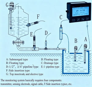
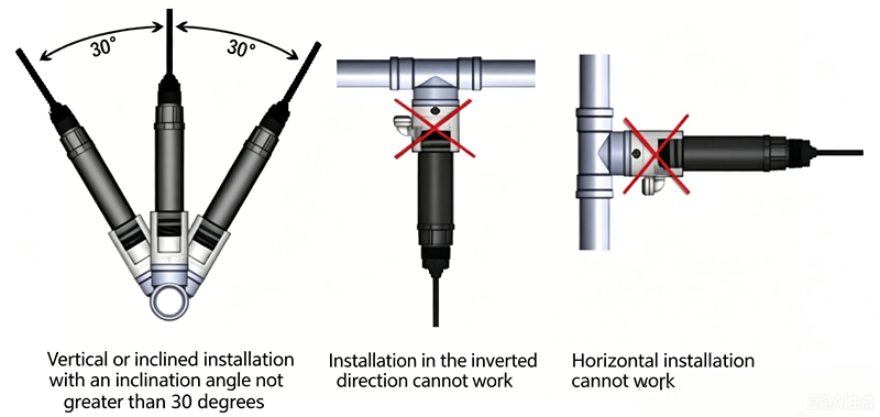
To ensure accurate pH measurement in pipelines and prevent data errors caused by air bubbles in the measuring cell, please follow the installation diagram strictly.
Notes:
(1) The electrode should be installed in a bypass line of the main pipeline. A valve should be installed at the front end to control the flow rate. The flow should be as low as possible; generally, a steady drip from the outlet is sufficient. The electrode must be installed vertically and immersed in the flowing liquid. The outlet should be higher than the inlet to ensure the electrode is fully submerged in the solution.
(2) The electrode should be calibrated before installation.
(3) The measurement signal is a weak electrical signal. The signal cable should be routed separately and must not be connected to the same cable connector or terminal block as power lines or control lines to avoid interference or damage to the measurement unit.
(4) If the measurement cable needs to be extended, please contact the manufacturer or specify before delivery (default length is 10m).
Key Features:
1.pH/ORP measurement, upper/lower limit control, current output, and digital communication
2.Manual or automatic temperature compensation
3.pH high and low limit alarms,Dual relay outputs with adjustable hysteresis
4.Isolated transmission port with maximum loop resistance >300Ω
5.Audible alarm can be enabled or disabled via the interface
Technical Specifications:
Measurement range: pH 0–14 pH; ORP –1900 to +1900 mV
Accuracy: ±0.02 pH; ±1 mV
Resolution: 0.01 pH; 1 mV
Stability: ≤0.02 pH/24h; ≤3 mV/24h
pH standard solutions: 4.01 / 6.86 / 9.18
Display: 128×64 dot matrix LCD
Temperature compensation: 0–100°C, manual/auto (NTC10K)
Signal output: 4–20 mA isolated output, max loop resistance 300Ω
Alarm output: High/low limit alarm contacts (3A/250VAC), normally open relays
Power supply: AC 220V ±10% 50Hz
Power consumption: ≤5.5W
Environmental conditions: (1) Temperature 0–60°C (2) Humidity ≤85% RH
Ordering Information
Smart transmitter (meter head)
Mounting method: Panel flush mounting for quick installation
Protection rating: IP65 (with back cover installed)
Electrode: Specify medium, pH range, temperature/pressure range
Electrode holder
Power supply: 9–36 VDC
Output: RS485 MODBUS RTU, optional 4–20 mA
Electrode cable: ____ m (standard 10 m, can be specified according to installation location)
Electrode protection tube (for immersion installation): Material ____, Length _____ m
Immersion type – Electrode protection tube holder
Flow cell type – Choose acrylic, PP, stainless steel, or other corrosion-resistant materials suitable for the medium
In-line type – Threaded connections
pH Standard Solutions
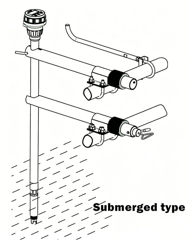
Accessories Selection Based on Installation Method:
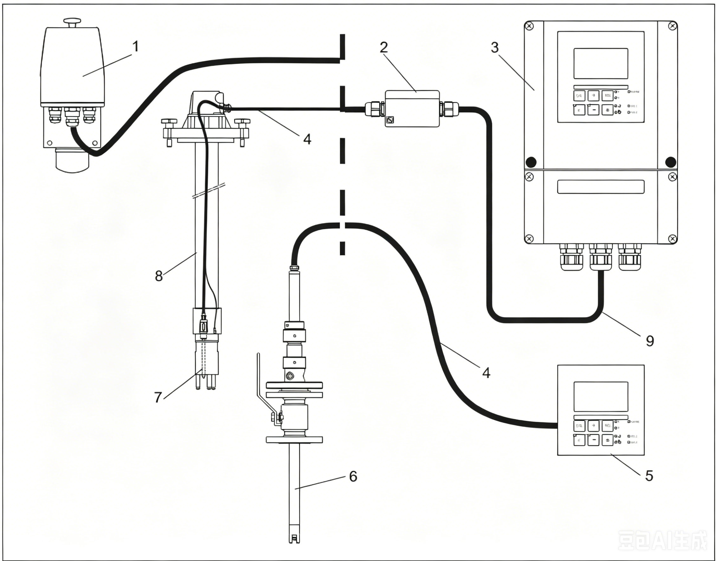
Installation Methods Summary Schematic Diagram of a Complete Measurement System
1.Flow-through mounting bracket
2.Junction box
3.Transmitter
4.Measurement cable
5.Transmitter
6.Retractable mounting bracket
7.Electrode
8.Immersion mounting bracket
9.Extension cable
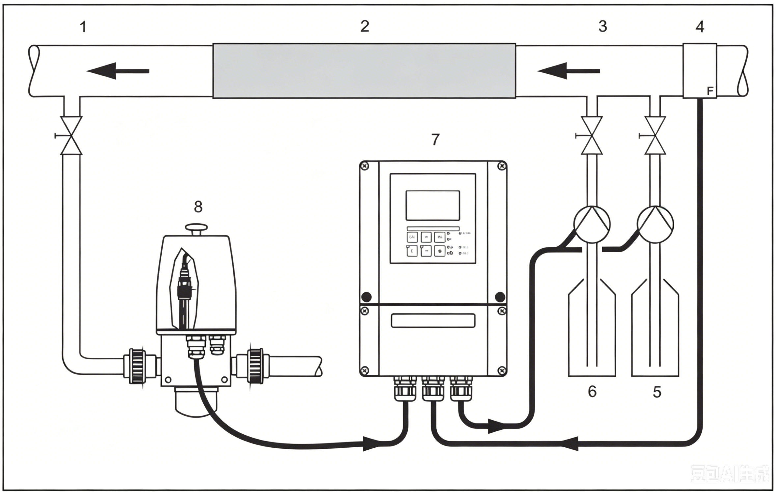
Application Example: PID Controller Main Flow Feedforward Control
1.Medium sampling point
2.Static mixer
3.Dosing point
4.Flow meter
5.Alkali solution
6.Acid solution
7.Transmitter
8.Mounting bracket
Post time: Jul-08-2026